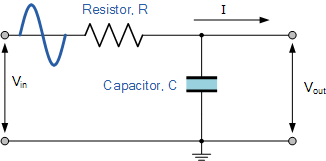
Passive Notch Filter Schematic
Notch circuit Notch filter (bandstop): what is it? (circuit & design) (a) schematic of the ir lna with the third-order passive notch filter
Wiring Diagram For Passive Notch Filter For Guitar - Database
Notch filter circuit band rlc stop electrical4u characteristics transfer function Filter pass rc passive circuit electronics filtro notch tiefpassfilter pasivo database frequency circuito logic dac cirrus theorem tiefpass passiver Notch filter design: 37 interesting facts to know – lambda geeks
Schematic diagram of the notch filter.
Filter notch circuit op amp diagram values using calculations component quite easy alsoNotch filter frequency edn Passive notch schematic lnaNotch filter audio build circuit diagram.
Notch filter (bandstop): what is it? (circuit & design)Build an audio notch filter 2 Wiring diagram for passive notch filter for guitarWiring diagram for passive notch filter for guitar.
Notch circuit filtre bande lambdageeks
Filter notch active circuit help understanding please amFilter notch band stop passive twin 60 frequency diagrams Build an adjustable high-frequency notch filterVariable notch filter circuit.
Notch filter: the circuit’s diagram and the design formula – electronicBand stop filter (a) schematic of the ir lna with the third-order passive notch filterThe circuit below is an active notch filter with a.

Free project circuit schematic: a twin t passive notch filter
Notch variableNotch electrical4u passive Notch filter (bandstop): what is it? (circuit & design)Crossover notch passive speaker capacitor.
Notch wiring passive database bandpass gyratorNotch filter passive twin Wiring diagram for passive notch filter for guitarFilter notch passive schematic lna.

Op amp notch filter circuit
Filter notch passive hz transcribed text showTl081 tunable notch filter ~ amplifiercircuits.com Design a passive notch filter reject 60 hz noise.Simple adjustable notch filter circuit diagram.
Notch active electrical4u transferNotch filter (bandstop): what is it? (circuit & design) Filter notch circuit adjustable diagram simple schematicsIs possible compute the bandwidth of a narrowband twin-t passive notch.

Filter notch tl081 tunable circuit audio frequency band hum circuits narrow gr next
Filter notch twin passive bandwidth function compute narrowband possibleNotch filter example electrical4u transfer function circuit .
.


Free Project Circuit Schematic: A Twin T Passive Notch Filter

Wiring Diagram For Passive Notch Filter For Guitar - Database

Schematic diagram of the notch filter. | Download Scientific Diagram

Simple Adjustable Notch Filter Circuit Diagram | Electronic Circuit

Build an Audio notch filter 2 | Electronic Circuit Diagrams & Schematics
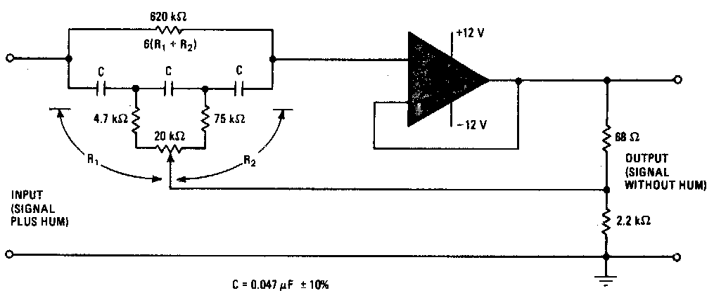
TL081 Tunable notch filter ~ AmplifierCircuits.com
Op Amp NOTCH Filter circuit - ZONA ELEKTRONIKA
